Screen Setup in LEDNet
Now that the adapters are set up in both Windows and LEDNet, and the screen is showing in the ON Cloud Platform, the screens can be configured in LEDNet.
Add Screen to LEDNET
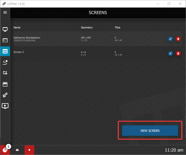
Navigate to the Screens Setup screen using the icon in the left-hand menu:

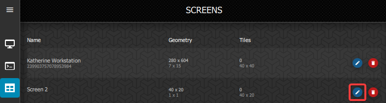
You will see a list of any screens that have already been set up. You can also edit or delete the screens from here.
Click the New Screen button to set up a new one.
You have the option to set up the screen manually or to use the screen wizard. We recommend that you use the Wizard unless you are extremely familiar with LEDNet and the screen settings you need to adjust.
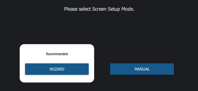
Click Wizard and it will take you to the Screen Setup details. The Wizard will not let you progress if something is missing so if your tiles are not connecting properly, you will need to resolve that before continuing.
Input the width and height of the screen based on the number of tiles that make up each side.
Type in the Screen Name. The name should be the same name used with the ON Cloud Platform.
If you tick the Clear Existing checkbox, it will clear any existing screens.
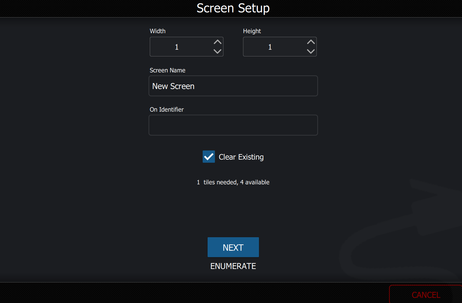
The ON Identifier is the unique ID generated when the screen is added to the ON Cloud Platform. This needs to be added to LEDNet so that it can communicate with ON about the screen.
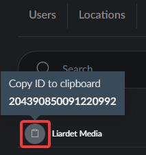
The Screen ID will be listed on the Screens menu in the Admin module in the ON Cloud Platform. Hover on the clipboard to the left of the Screen name to view the ID. Click it to copy the ID to your clipboard, then paste the ID into the ON Identifier field in LEDNet.
Once these details are input, click Enumerate to check the number of Adapters and Tiles that are found for the screen. If all details are correct, then you can create the Sections for the screen.
Click Next to add sections.
Add Sections to Screen
A Section is a group of Tiles that share an adapter. A Screen is made up of one or more Sections. Depending on the number of tiles in your screen, you may only have one section for your screen. If this is the case, you still need to specify the details for that section.
As you add each section, the total number of tiles and sections will be indicated under the section summary.
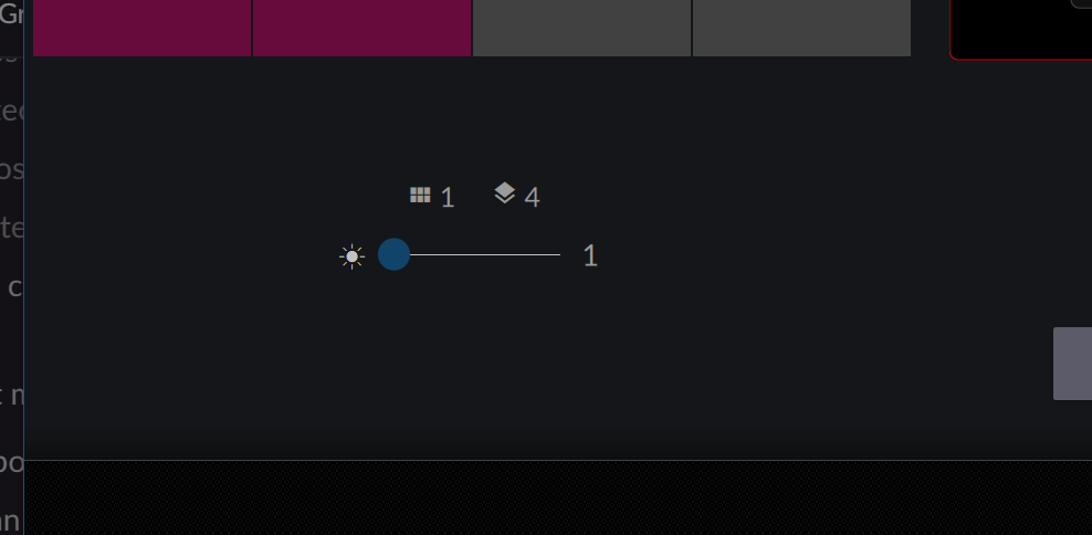
If you are having difficulty seeing the Tile IDs, you can adjust the brightness using the slider under the section summary.
Sections must follow the wiring pattern. You cannot have a section that encompasses tiles that are not wired contiguously.
Sections are used to:
- Group the screen into areas of similar wiring
- Define a logo box (that won't be captured by the proof engine)
- Swap strands if they are in the wrong order
Strands are separate groups of tiles on the same adapter that are wired contiguously from the switch to the end of the strand. Each strand has its own ethernet connection to the switch and usually has its own power source.
Sections cannot span strands but a strand can have multiple sections on it. Tiles within each section must be contiguously connected.
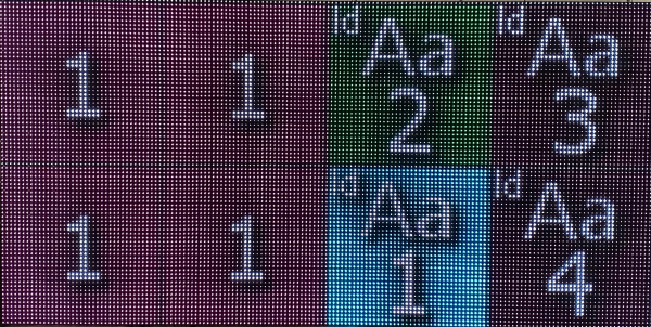
You will need to be able to view the screen to update the sections.
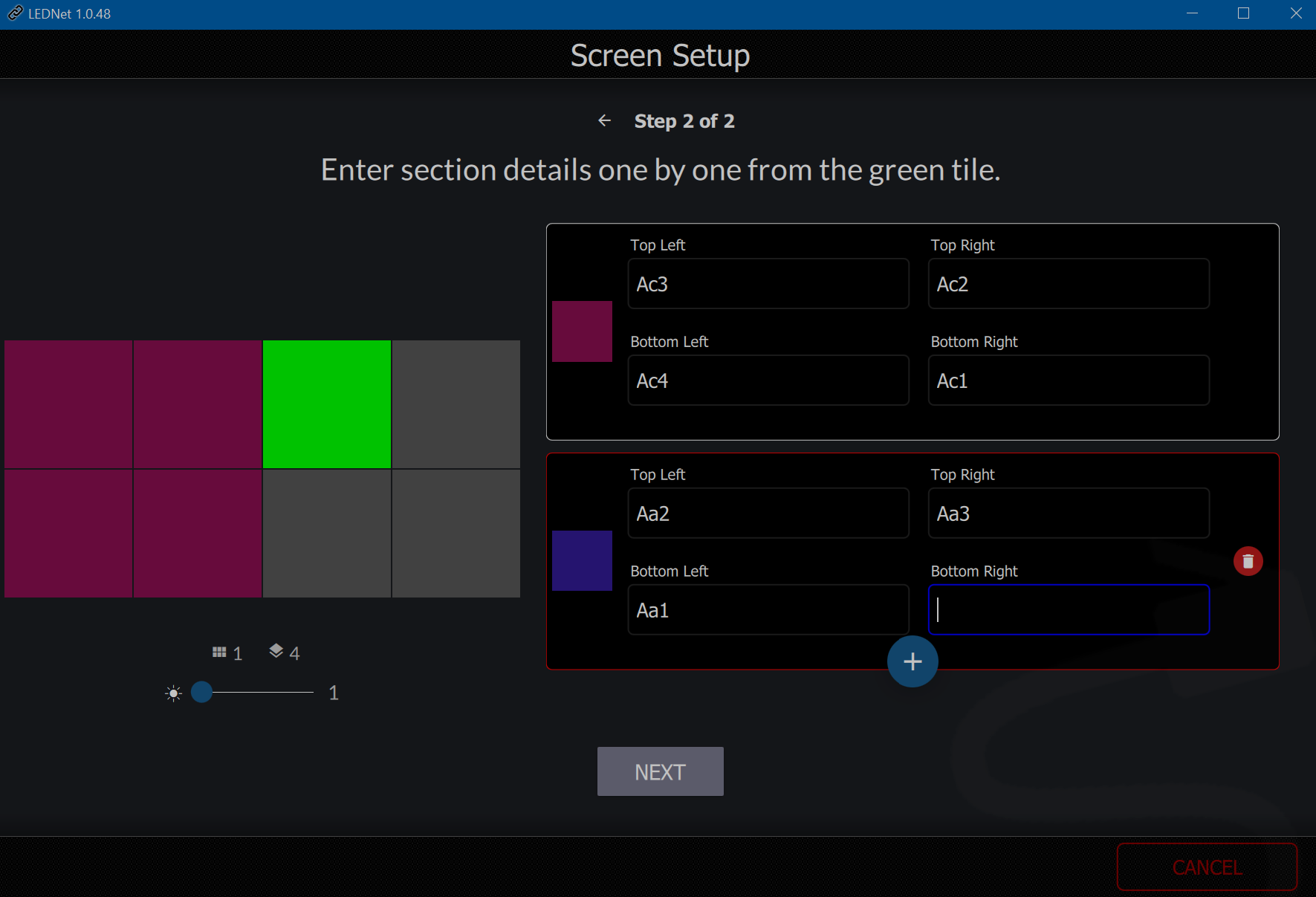
The tiles will be displaying their tile ID (e.g. A1, A2, B1, B2). Use the ID numbers to outline the section by inputting the first tile of the first section (usually A1) into the Top Left file. Then input the tile ID number for the top right tile, the bottom left and the bottom right tiles.
If you have more than one section on the screen click the + button to add the next section and continue to input the tile ID numbers into the correct positions.
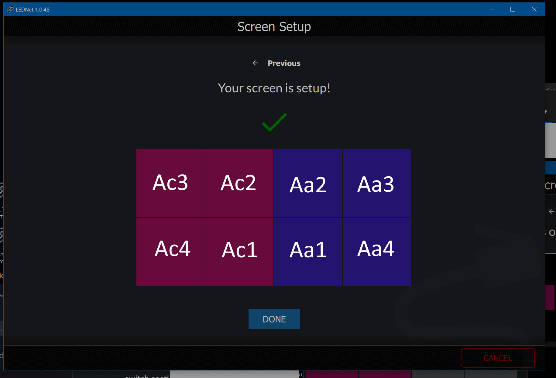
When you have added the sections, click Next. You should receive a message that setup was successful, and it should enumerate and confirm that the number of tiles you expect to be counted are there.
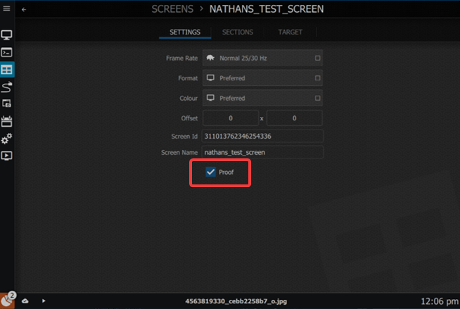
It's best to turn on Proof of Display for your screen. You can find this in the Screens Settings. Tick the checkbox next to Proof to enable proof of display functionality.
Continue to edit additional details of the screen.
Edit Sections of Screen
To edit the Sections, click the edit icon for the screen you just set up and choose the Sections heading along the top.
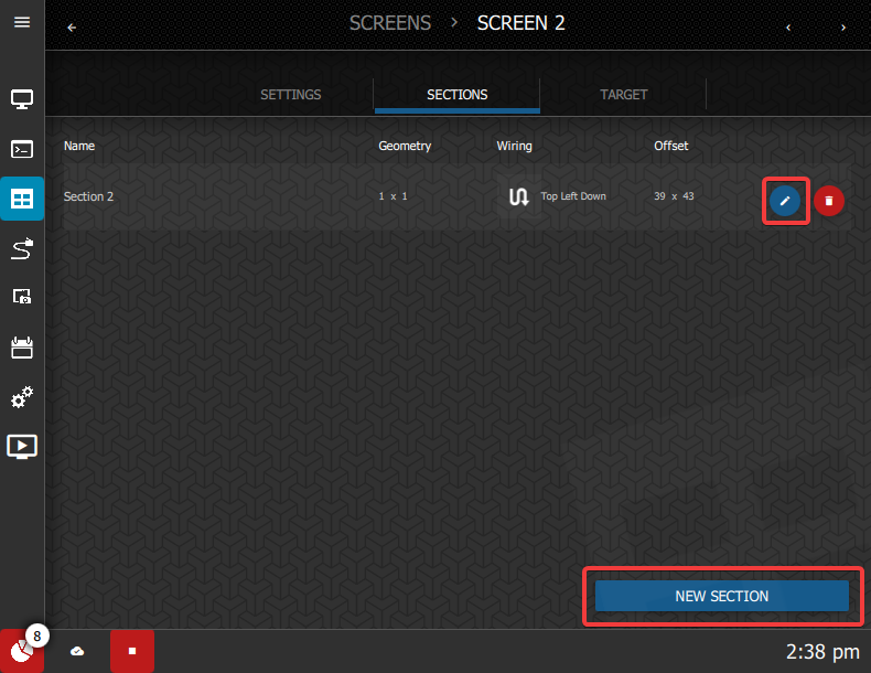
This will take you to the Sections menu. If you need to return to the list of screens, click the back arrow near the top left of the window or click on the link in the breadcrumb menu.

Click the edit icon for the section you wish to edit.
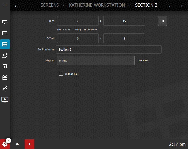
The edit screen allows you to define and change the following details:
- Wiring Pattern
- Section Offset (in pixels)
- Section Name
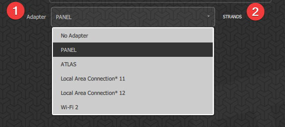
- Adapter
- Strands
- Whether the section is a logo box or not
A logo box is a section that is ignored by the Proof of Display engine. This allows you to use any number of tiles to display a logo but will not track that section in the Proof of Display data. If you want your entire screen to be included in the Proof of Display data, do not tick this box.
Wiring Pattern
Select the wiring pattern by clicking the wiring button and selecting the layout of the wiring for that section.
The layout should begin with the first tile connected to the adapter and then continue in the direction of the second and the following tiles.
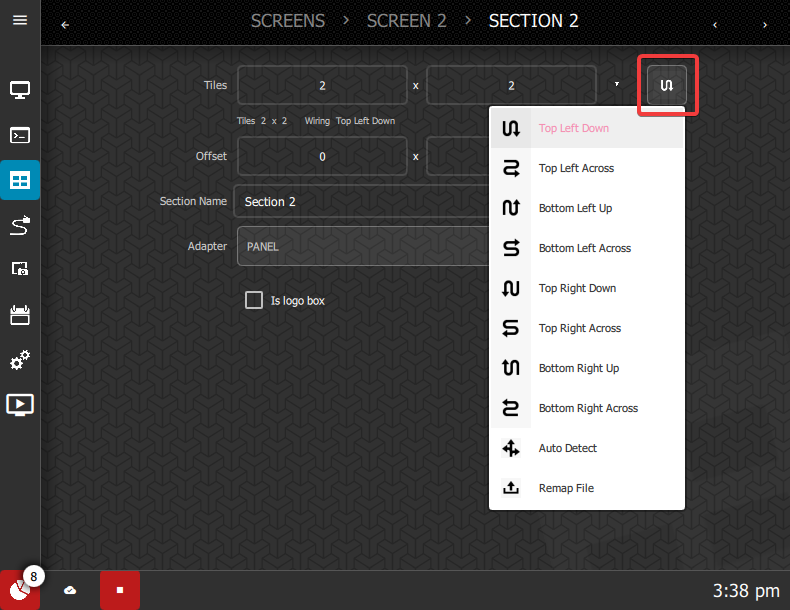
The Auto Detect option is not likely supported by newer tiles. However, if your tiles support it, you can use auto detect to define the wiring layout.
If your tiles are wired in a non-standard way that's not listed on the menu, (i.e. it may be an architectural installation) the Remap File option is used to upload a map file.
Input the offset, in pixels, for the section. This value can be 0 x 0 if there is no offset on the section.
Define the name of the Section. This could be something referring to its position in the screen for easy future reference, e.g. "Top Left".
From the dropdown Adapter menu, select the adapter this section is connected to.
Some of the sections will represent different strands in LEDNet. If they are in the wrong order, they need to be mapped into the right order. You can do this by clicking the Strands button.
Clicking the Show Strand Pattern checkbox will display two numbers on each screen. The larger number is the current section and the smaller number is the strand order.
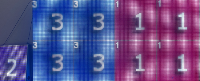
By looking at the live screen, you need to map the order in LEDNet. Click the section number that represents the strand you need to move, and then the section to swap it with until you have rearranged them in the right order.
Now that the screen is set up in LEDNet and the Sections are defined, you can adjust the settings related to the sunrise/sunset times, the cloud connection, proof of display settings and behaviour.